
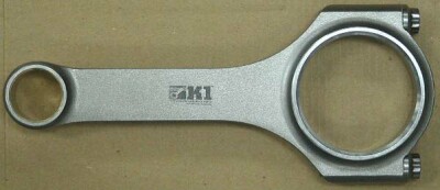
K1 Connecting Rod Bolt Torque, Assembly and Installation
![]()
Rod Assembly , Rod Bolt Stretch, Torque and Angle Specifications
In order to get the best service and longest life from your K1 Technologies connecting rods, please read and follow the following guidelines closely.
FAILING TO FOLLOW THESE INSTRUCTIONS CAN RESULT IN ENGINE FAILURE
Connecting Rod Installation: Getting Started
Before disassembling your connecting rods, number the rod and matching cap. DO NOT use metal stamps to mark the rods and caps!
Do not mix the rods and caps. The rod and cap is precision machined to extremely tight tolerances. Each cap and rod is unique and the caps and rods can not be mixed so be careful to keep the rod and cap matched together just as you receive them from K1.
Always disassemble and clean all rod and bolt surfaces before assembling
CLEARANCES: Clearances are controlled by the bearing shells, not by housing bore diameter of the connecting rod. The housing bore diameter controls bearing crush and helps prevent the bearing from spinning. We do not recommend the use of Plasticgage for checking bearing clearance. Measure the housing bore of the rod with a bore gage and use a micrometer to measure your crankshaft to insure you have the proper bearing clearance. Normally, .001” per inch of crankshaft diameter is recommended when measured at the crown of the bearing.
Connecting Rod Assembly
Seat the cap on the rod by hand making sure the alignment dowels line up with the counter bores in the rod then using a rubber mallet, tap the cap into place. Lubricate the threads and under head of the bolt with the lube provided by K1. Do not use Loctite or oil on bolts.
Clean all parts thoroughly to remove all dirt and foreign oils. Spread the supplied bolt lube on threads and under head of bolt and tighten per instructions below. Bolts are like very stiff springs. Stretching them the proper amount provides the clamp load that is required to keep the parts bolted together.
A note regarding using the rod bolt torque method to tighten rod bolts
Using a torque wrench to measure connecting rod bolt torque does not measure clamp load, it measures friction. Torque does not measure clamp load and only measures the amount of friction that must be overcome to turn the bolt. The friction of the mating surfaces of the threads, rod spotface and bolt flange change with each tightening. When you consider the fact that different amounts and different types of lubes also change the friction, using the torque method is like trying to hit a moving target that you cannot see. K1 Technologies does not recommend the use of or provide torque values for tightening bolts.
Measuring Connecting Rod Bolt Torque Stretch and Torque Angle
The stretch method or the torque and angle method are both much more accurate ways to properly tighten rod bolts. To use the stretch method, measure and note the free length of each bolt before tightening with a rod bolt stretch gauge or a micrometer with ball end attachments. Then, using the chart below, tighten the bolt until the proper stretch is achieved. Use a rod bolt log like the one shown at the bottom of this page to record the free length of your bolts.
To use the torque and angle method, simply torque the bolts the amount listed in the chart below then, using a Snap-On #TA360 torque angle gauge, turn the bolt the listed number of degrees.
Connecting rod installation bolt stretch & torque and angle specsRod Bolt Type column shows bolt diameter, length and material type. Length shown below is the under head length. Measure from under the head of the bolt to the tip of the bolt. Head Stamp refers to the identification marks stamped on the head of the bolt. Recommended Stretch and Torque and Angle columns show the proper specifications to install that bolt size and material type according to the measurement method you are using. |
|||
| Rod Bolt Type | Head Stamp | Recommended Stretch | Torque and Angle |
| 3/8 X 1.500” ARP 8740 | ARP | .0046” to .0050” | 25 ft lbs + 40 Deg |
| 3/8 X 1.500” ARP 2000 | ARP2000 | .0055” to .0059” | 25 ft lbs + 55 Deg |
| 3/8 X 1.600” ARP 8740 | ARP | .0048” to .0052” | 25 ft lbs + 40 Deg |
| 3/8 X 1.600” ARP 2000 | ARP2000 | .0056” to .0060” | 25 ft lbs + 55 Deg |
| 7/16 X 1.550” ARP 2000 | ARP2000 | .0056” to .0060” | 30 ft lbs + 55 Deg |
| 7/16 X 1.600” ARP 8740 | ARP | .0050” to .0054” | 30 ft lbs + 50 Deg |
| 7/16 X 1.600” ARP 2000 | ARP2000 | .0060” to .0064” | 30 ft lbs + 60 Deg |
| 7/16 X 1.800” ARP 8740 | ARP8740 | .0059” to .0063” | 30 ft lbs + 50 Deg |
| 7/16 X 1.800” ARP 2000 | ARP2000 | .0068” to .0072” | 30 ft lbs + 60 Deg |
Connecting Rod Bolt Stretch Log Sample
We would like to thank K1 Technologies for allowing us to post this connecting rod bolt tightening reference information on our website.
 Item added to cart
 copyright © Motorsports Parts Corporation T/A Campbell Enterprises. All rights reserved